0 引言
1 实验部分
1.1 材料制备
表1 EPDM绝热材料配方(phr)Table 1 The formulation of EPDM materials |
| Baseline formulation | CNTs formulation | |
|---|---|---|
| EPDM rubber | 100 | 100 |
| Aramid fiber | 10 | 10 |
| Fumed silica | 20 | 20 |
| Paraffin oil | 10 | 10 |
| Phenolic resin | 20 | 20 |
| DCP | 6 | 6 |
| CNTs | 0 | 10 |
Notes:phr is defined as parts per hundred rubber. |
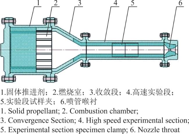
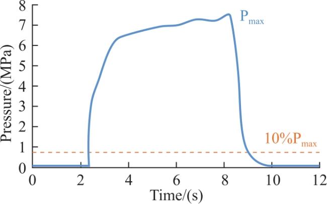
1.2 高速气流冲刷烧蚀实验
1.3 烧蚀性能及炭化层特性表征
2 结果与讨论
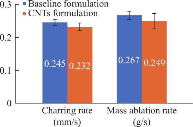
2.1 高速气流冲刷实验结果
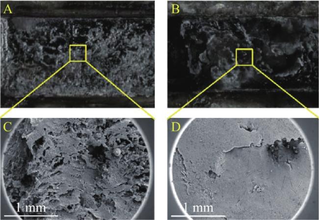
2.2 炭化层电镜及EDS分析
2.3 原始炭区域形貌及元素分析
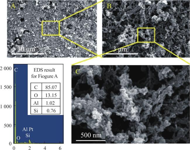
图5 基础配方炭化层原始炭区域的SEM图像及EDS结果Fig.5 Electron microscopy and EDS results of the original C region in the char layer of the baseline formulation |
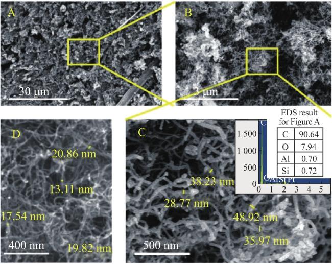
图6 烧蚀试验后CNTs配方炭化层原始炭区域的SEM图像和EDS结果及实验前CNTs形貌:A,B为实验后CNTs配方炭化层;C,实验后CNTs照片;D实验前CNTs照片Fig.6 SEM photos and EDS results of original C-region char layer of CNTs formulation after ablation test,pre-experiment CNT photos:A,B:post-experiment char layers of CNTs formulation; C:post-experiment CNTs photos; D:pre-experiment CNTs photos |
2.4 SiO2富集区域形貌及元素分析
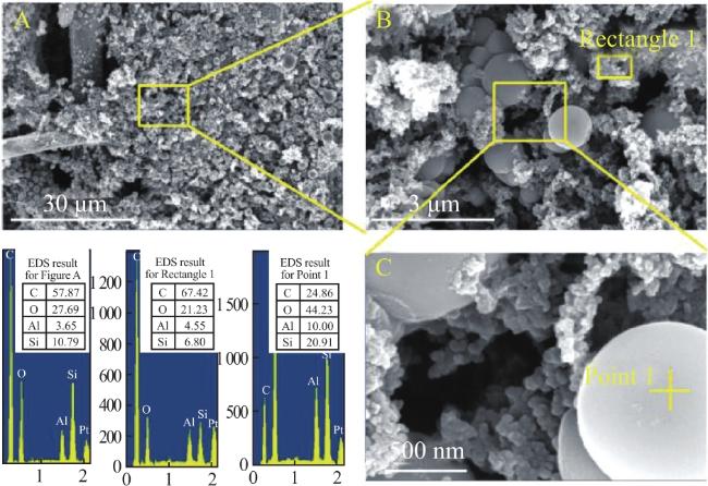
图7 基础配方炭化层SiO2富集区域的SEM图像及EDS结果Fig.7 SEM photos and EDS results of SiO2 aggregated region in the char layer of the baseline formulation |
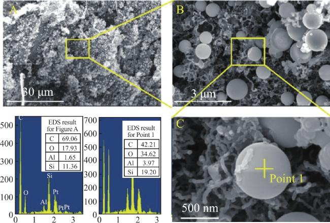
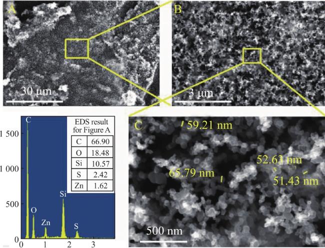
图9 CNTs配方炭化层SiO2富集区域的SEM图像及EDS结果-微观结构2Fig.9 SEM photos and EDS results of SiO2 aggregated region in the char layer of CNTs formulation-microstructure 2 |
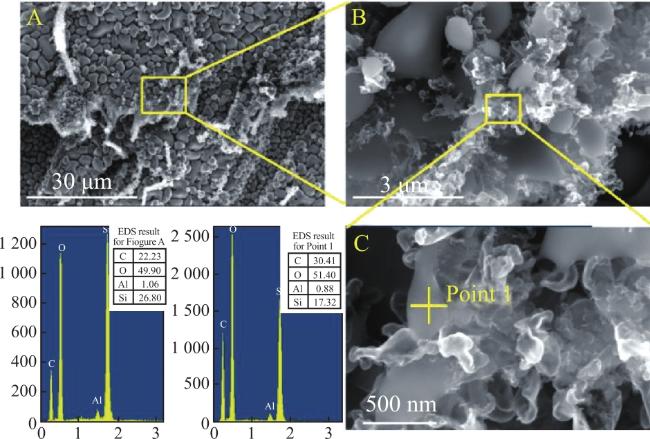
2.5 Al2O3沉积区域形貌及元素分析
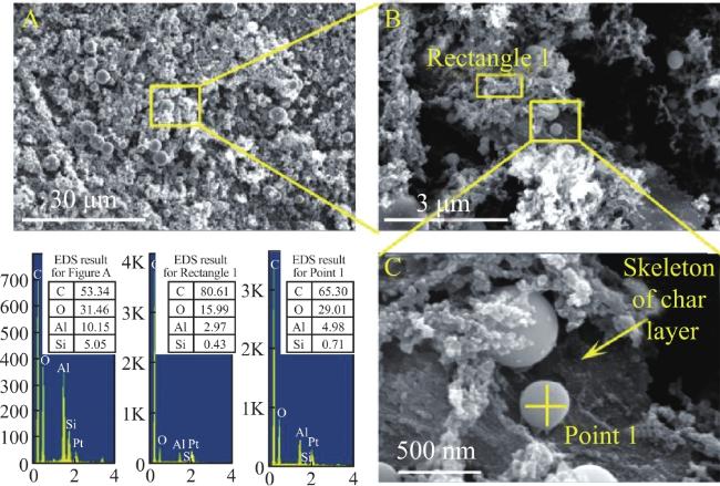
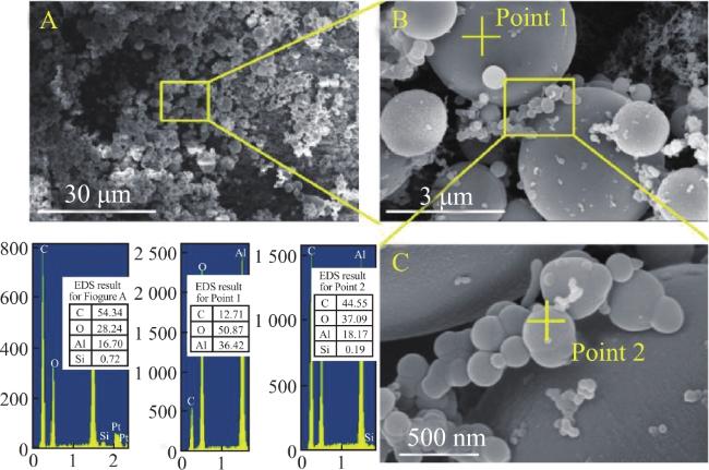
图11 基础配方炭化层Al2O3沉积区域的电镜照片及EDS结果-微观结构1Fig.11 SEM photos and EDS results of the Al2O3 deposition region in the char layer of the baseline formulation-microstructure 1 |
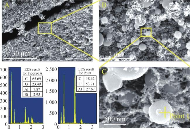
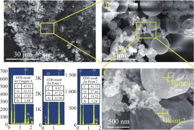
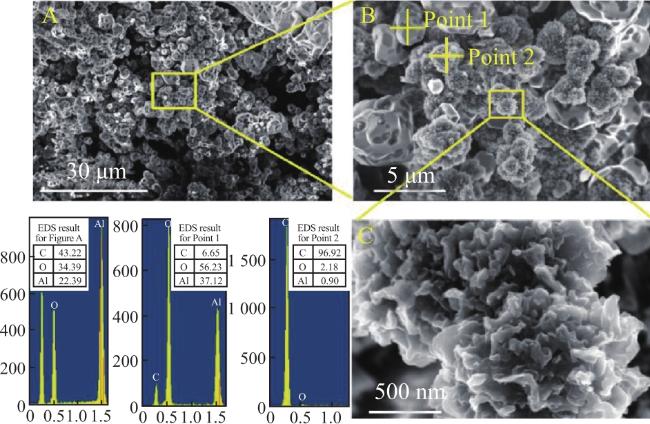
图13 基础配方炭化层严重Al2O3沉积区域的电镜照片及EDS结果-微观结构2Fig.13 SEM photos and EDS results of severe Al2O3 deposition area in the carbonized layer of the baseline formulation-microstructure 2 |