

0 引言
作为航空航天领域的研究前沿,高超声速飞行器一直是科研人员关心与研究的热点。目前业界定义飞行马赫数大于5时为高超声速飞行,高超声速飞行工况相较于亚音速飞行工况,飞行器受到激波强度与波阻激增,导致常规外形的飞行器的升阻比显著下降,面临难以跨越的高超声速“Küchemann升阻比屏障”问题[1]。为解决这一问题,Terence Reginald Forbes Nonweiler[2]于1959年首次提出乘波体概念。乘波体的设计原理是通过飞行器的前缘面与激波重合,将高压气流约束在飞行器的下表面,从而赋予乘波体高升力、低阻力的特性。这一特性使其成为高超声速飞行器的理想气动布局。然而,乘波体上表面通常采用自由流面方法设计生成,缺乏纵向曲率变化,导致乘波体的容积特性不足。为平衡气动特性与结构空间的需求,需在保持下表面乘波特性的前提下,通过重构上表面设计型线,对上表面进行脊形设计,改进乘波体的容积特性。
1991年,Frederick Roos和Jerome Kegelman[3]针对脊形前体的气动特性展开了专门的研究。研究显示脊形前体在大攻角工况下,其独特的外形致使上表面流场出现较强的涡旋。这种涡旋使上表面有较高的负压,进而使脊形前体拥有比圆锥构型和椭圆锥构型更好的方向稳定性和更大的法向力。
现有的脊形吻切锥乘波体设计方法大致可分为三类。Ramakrishnan Ravi和William H. Mason[4]提出了利用超椭圆方程获得脊形前体横截面曲线,并通过切线尖拱曲线与直线段的组合形成俯视投影轮廓线的方法,该方法对设计型线进行了约束,在一定程度上限制了设计空间。另一种方法由符翔等[5]提出,将超椭圆方程与吻切锥乘波构型相结合,上表面采用超椭圆方程设计,下表面采用吻切锥乘波体设计,上下表面的交线即为前缘线,但上表面设计自由度仍受超椭圆方程的限制。最后一种,唐培结[6]基于 CST(Class-Shape Transformation)方法对乘波飞机构型进行了设计与优化,该方法无需对基准面设计型线进行约束,且输入较少参数即可实现曲线的良好拟合,但其控制参数间接作用于曲线样式,变化不够直观,调节难度较大。
上述方法虽各有优势,但普遍存在设计自由度受限或参数调节复杂的问题,针对以上方法的不足之处,本文将B样条曲线设计方法引入脊形吻切锥乘波体设计,并生成多个不同外形的脊形吻切锥乘波体,采用计算流体动力学(CFD)方法,对乘波体的气动性能进行检验。
1 基于B样条曲线的脊形乘波体设计
为了更好地介绍本文提出的基于B样条曲线的脊形乘波体设计方法,下面对B样条曲线方法进行简单的介绍。
1.1 B样条曲线定义
B样条曲线通过引入节点向量,实现了复杂几何形状的参数化表达,使其具有统一和有效的标准算法和解决方案[7-8],B样条曲线设计方法已被广泛用于翼型与机身等外形设计中。例如,Marlena Gomez等人将B样条与自由形变(FreeForm Deformation,FFD)方法结合,通过有限控制点实现翼型外形的生成与优化[9];Dev Rajnarayan等将B样条曲线引入通用翼型参数化方法,高效近似多类型翼型轮廓并增强了设计灵活性[10];Mario J. Martin等将B样条曲线用于机翼及翼身组合体的三维气动外形参数化建模,有效提升了复杂曲面的拟合精度与几何描述的灵活性[11]。目前,B样条曲线基函数普遍采用DeBoor-Cox递推定义[12],如式(1)所示:
式中:Ni,k(t)的双下表中,i表示序号,k表示次数。
C(t)= Ni,p(t)Pi
式中:t表示节点矢量;Pi为B样条曲线的控制点;p为曲线阶数;n+1为控制点个数;n+p+1为节点数。
1.2 贝塞尔曲线定义
贝塞尔曲线是特定参数下的B样条曲线,一个包含了n+1个控制点的n阶贝塞尔曲线可表示为n阶伯恩斯坦(Bernstein)多项式的线性组合[19],如式(3)所示:
B(t)= Pi ti(1-t)n-i,t∈[0,1]
式中:n是贝塞尔曲线阶数;Pi是控制点; = 是组合数;n!表示阶乘;t是贝塞尔曲线的参数,当t=0时,对应着贝塞尔曲线的起点;当t=1时,对应着贝塞尔曲线的终点。
贝塞尔曲线通过起点、终点和控制点直接定义形状。在设计之初可通过直接调整控制点调整曲线走势,无需像B样条曲线一样处理节点向量配置,所以将贝塞尔曲线引入经典吻切锥乘波体设计型线中。
1.3 基准面型线设计
乘波体构型通常由上、下表面和基准面组成,其中基准面为各设计型线生成的参考平面,用于统一型线的空间定位。本文的乘波体设计方法采用正向设计,模型表面设计型线包括上表面底部型线、激波底部型线以及前缘线。
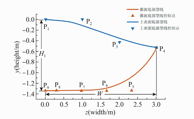
激波底部型线(Inlet Capture Curve,ICC)采用四阶贝塞尔曲线构建,曲线形状由P4至P9共6个控制点确定。上表面底部型线(即流线追踪起始投影线,Flow Capture Tube,FCT),采用三阶贝塞尔曲线构建,曲线形状由P1~P4共4个控制点确定。结合乘波体半模展向宽度为W,上表面底部型线与激波底部型线之间的最大距离为H1,通过预设9个控制点与W和H1的比例关系,即可确定所有控制点的坐标。
为便于后续的计算分析,通过参数W和H1对各控制点进行归一化操作,如式(4)所示:
P2,P3的坐标利用P1和P4的坐标进行归一化操作;P5,P6,P7的坐标利用P1,P4与P8的坐标进行归一化操作,如式(5)所示:
1.4 前缘线及下表面底部型线设计
以吻切锥乘波体设计[20]为例,空间中存在若干个假定的圆锥体,超声速气流流经每一个圆锥体时会产生一个圆锥激波,沿每一个圆锥激波截取特定弧段,并将若干个激波弧段光滑连接,即可形成吻切锥乘波体的激波底部型线,这些圆锥体被称为吻切锥。每一个激波弧段上的点和相应吻切锥轴线都能确定一个平面,该平面被称为吻切面[21]。在各个吻切平面内,吻切锥顶点的位置由激波角和该段激波的激波曲率半径确定。在各个吻切平面内,吻切锥顶点与激波底部型线上对应的点连线组成圆锥激波的母线。以上表面底部型线为基线,沿逆来流水平方向构造一个三维空间曲面,即乘波体的上表面。上表面与每一条圆锥激波母线相交可确定一个点,该点称为前缘点。将所有前缘点依次连接即可形成一条曲线,该曲线称为前缘线。以各前缘点为起始位置,在其对应的吻切平面内进行正向流线追踪,可得到相应的流线;将这些流线平滑连接,即形成一个曲面,该曲面即为乘波体的下表面。乘波体下表面与基准面的交线,即为乘波体的下表面底部型线。基准流场参数通过求解Taylor-Maccoll[22]流动控制方程得到,如式(6)所示:
式中:Vr,Vθ,a分别是以临界声速无量纲化的径向速度分量,切向速度分量和声速;θ为吻切锥顶点引出的射线与吻切锥轴线之间的夹角。Taylor-Maccoll方程为二阶常微分方程组,可采用四阶Runge-Kutta法对该方程组进行求解[23]。
1.5 基于B样条曲线的脊形乘波体上表面底部型线设计
脊型乘波体的上表面设计包括脊形上表面底部型线(Chined Flow Capture Tube,CFCT)与上表面对称设计型线(Symmetric Line of the Upper Surface,SLUS)两部分。上表面底部型线采用三阶B样条曲线构建,型线形状由P10至P13以及P4共5个控制点确定;对称面型线采用二阶B样条曲线构建,型线形状由控制点 、 、 共3个控制点确定,上述B样条曲线的节点矢量均为均匀分布。结合乘波体半模展向宽度为W,脊形上表面底部型线与上表面底部型线之间的最大距离为H2,设计马赫数Ma以及激波角β。需要指出的是,乘波体长度L为未知量,其大小由H1和β共同决定。通过预设6个控制点与W,H2及L之间的比例关系,即可确定脊形乘波体的长度和相应控制点的坐标,其具体分布如表2所示,由此得到的两条设计型线如图2所示。
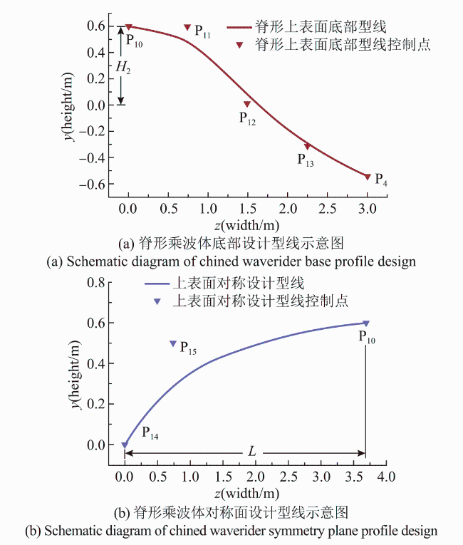
为便于后续的计算分析,通过参数W和H1对各控制点进行归一化操作,如式(7)所示:
P13的坐标利用P10,P4的坐标进行归一化操作;P11和P12的坐标利用 和 进行归一化操作;P15的坐标利用P10,P14的坐标进行归一化操作,如式(8)所示:
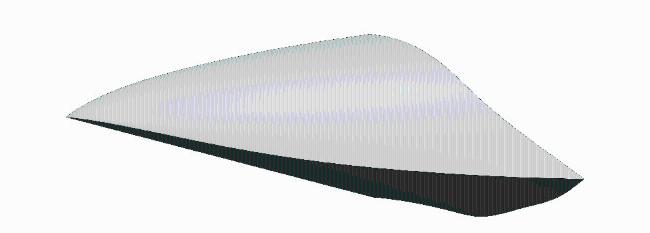
综上,通过给定来流马赫数Ma,激波半顶角β,乘波体半模展向宽度为W,上表面底部型线与激波底部型线之间的最大距离为H1,脊形上表面底部型线与上表面底部型线之间的最大距离为H2等关键设计参数,即可确定脊形乘波体半模的各设计型线。以Ma=8、β=20°、W=3m、H=1.34m、H2=0.6m为例,将计算得到乘波体的前缘线、上表面、下表面参数导入三维建模软件。由于模型具有对称性,这里仅生成的脊形吻切锥乘波体模型的一半,其体积为4.725m3,模型如图3所示。
2 脊形吻切锥乘波体设计方法验证
2.1 数值方法与算例验证
本节针对上一节生成的脊形乘波体开展数值模拟,以验证所提出设计方法的有效性,并评估其外形的气动性能。考虑到模型周围流场的可压缩特性,数值计算基于密度基框架下的三维可压缩 Navier-Stokes 方程。控制方程采用有限体积法进行空间离散,对对流项使用二阶精度的AUSM 格式以提高计算精度。在稳态求解过程中,数值迭代采用显式伪时间推进方法以实现收敛。将流动介质视为定比热比γ=1.4的理想气体。为保证计算精度和强间断计算的稳定性,湍流模型采用SSTk-ω模型,在处理黏性效应相关问题时,分子黏性系数则依据Sutherland 公式确定。
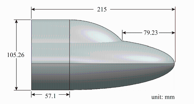
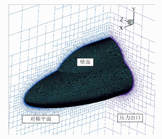
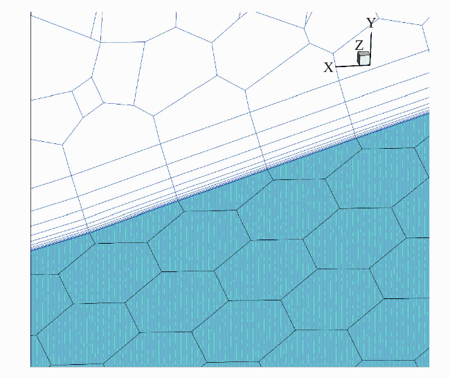
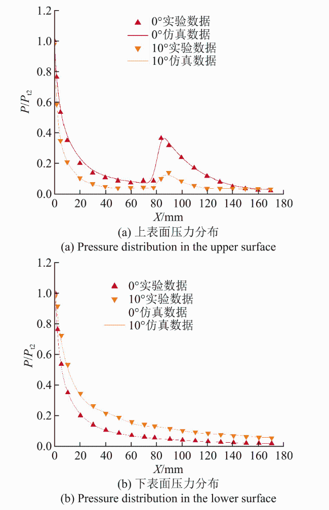
计算结果以无量纲压力P/Pt2形式表示,其中P为对称面处监测点的来流静压,Pt2为双椭球模型顶点来流的皮托压力。双椭球模型对称面上监测点处的无量纲压力对比结果如图7所示。其中,坐标原点为双椭球模型的顶点,横坐标x正方向设定为气流流动方向,纵坐标为无量纲压力。从图中可以观察到,除在双椭球交界面顶点处外,其余监测点处的数值模拟结果与文献中风洞实验数据的相对误差均不超过10%。这一结果表明:数值仿真结果与实验结果大体一致,表明本文使用的数值计算方法误差较低,可作为后续脊形乘波体的数值计算方法。
2.2 脊形乘波体方案设计与网格收敛性验证
表3 不同上表面的控制点P12调整参数Table 3 Adjustment parameters of control point P12 for different upper surfaces |
| Parameter | Y |
|---|---|
| Plane 1(P12) | 0.9 |
| Plane 2(P12) | 0.75 |
| Plane 3(P12) | 0.5 |
| Plane 4(P12) | 0.35 |
| Plane 5(P12) | 0.2 |
| Plane 6(P12) | 0.05 |
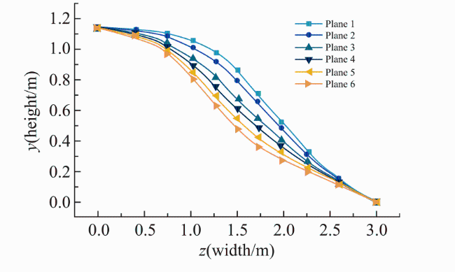
表4 不同上表面的乘波体容积率Table 4 Volume-to-surface ratios of waveriders with different upper surfaces |
| 参数 | V(m3) | S(m2) | η |
|---|---|---|---|
| Plane 1 | 10.602 | 8.186 | 0.295 |
| Plane 2 | 10.288 | 8.186 | 0.289 |
| Plane 3 | 9.764 | 8.186 | 0.279 |
| Plane 4 | 9.450 | 8.186 | 0.273 |
| Plane 5 | 9.136 | 8.186 | 0.267 |
| Plane 6 | 8.822 | 8.186 | 0.261 |
以图8中Plane 4脊形上表面的乘波体为对象,对脊形乘波体进行网格收敛性分析。分别生成3套不同尺度的网格:粗网格Coarse,网格数量为150余万;中等网格Medium,网格数量为320余万;细网格Refined,网格数量为570余万。
表5 不同网格下的气动参数表Table 5 Aerodynamic parameters under different grid settings |
| 参数 | 体网格 | ||
|---|---|---|---|
| 细网格 | 中等网格 | 粗网格 | |
| CL | 0.11410 | 0.11352 | 0.11348 |
| CD | 0.07608 | 0.07532 | 0.07424 |
| L/D | 1.49973 | 1.50716 | 1.52855 |
| Cm | 7.32×10⁻³ | 7.17×10⁻³ | 7.03×10⁻³ |
表6 不同网格下的气动参数差异表Table 6 Comparison of aerodynamic parameters under different grids |
| 参数 | 体网格 | ||||
|---|---|---|---|---|---|
| 细网格 | 中等网格 | 粗网格 | |||
| ΔCL | — | 0.51% | 0.54% | ||
| ΔCD | — | 1.00% | 2.42% | ||
| ΔL/D | — | -0.49% | -1.92% | ||
| ΔCm | — | 2.04% | 3.96% | ||
从上述的计算结果可知,Medium网格相比于Coarse网格的气动参数差异更小,更接近于Refined网格的气动值,同时网格数量中等,节省计算资源,故后续数值仿真将基于Medium网格开展。
2.3 气动性能分析
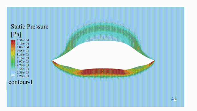
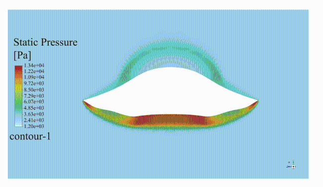
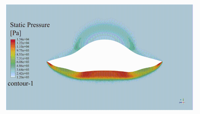

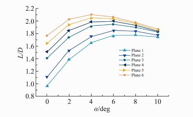
图12 升力系数随攻角变化曲线图Fig.12 Curve graph of lift coefficient varying with angle of attack |
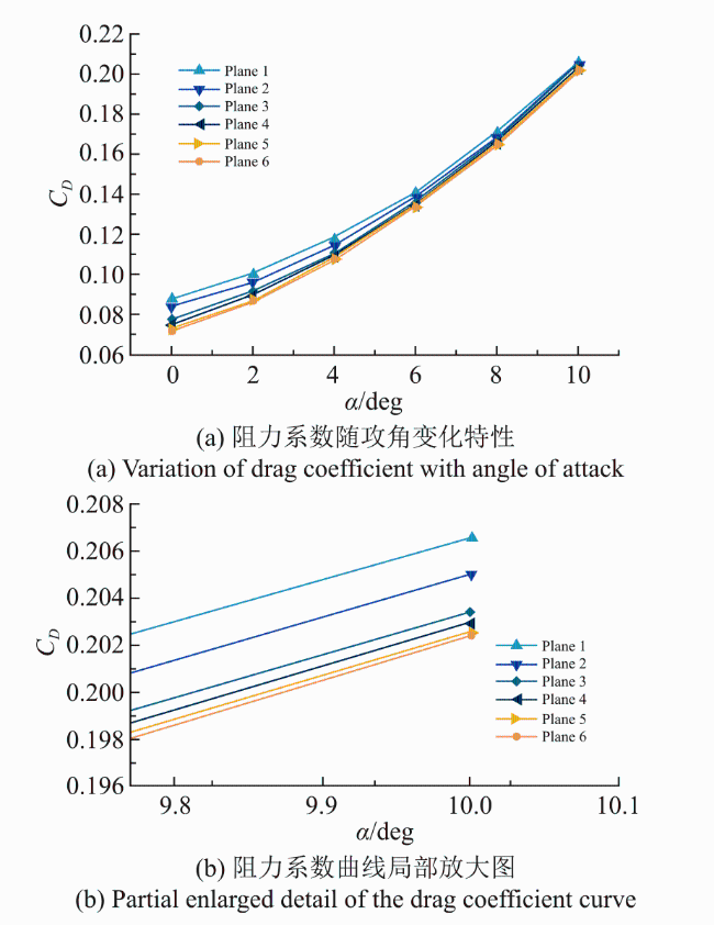
图13 阻力系数随攻角变化曲线Fig.13 Curve graph of drag coefficient varying with angle of attack |


0°攻角时,Plane 1的阻力系数CD=0.08854较Plane 6的阻力系数CD=0.07166,脊形外形的变化导致阻力系数升高了23.55%。这一差异主要源于脊形上表面曲率不同所导致的上表面压缩波分布不一致,进而导致压力分布及阻力系数的变化。随着攻角增大,阻力系数逐渐增大,但是各外形之间阻力系数差异逐渐较小,阻力系数在0.2024至0.2066之间,与最大阻力系数的差异在2%左右。这表明在大攻角下,上表面压缩波引起的压力分布差异减弱,使脊形外形对阻力系数的影响趋于弱化。
0°攻角时,Plane 1的升阻比L/D=0.96412较Plane 6的升阻比L/D=1.76036,升阻比降低了45.23%。随着攻角增大,升阻比的变化趋势均为先增大后减小,但是脊形上表面外形变化导致最大升阻比的值与其所对应的攻角均发生变化。如图8以及图14所示,脊形上表面外形越“凸”,最大升阻比的值越小,由Plane 6的2.1007减小到Plane 1的1.78535;同时Plane 6最大升阻比对应的4°攻角增大了Plane 1最大升阻比对应的6°攻角。上述数据表明脊形上表面外形对最大升阻比及其对应的攻角影响较大。这主要是由于上表面“凹凸”程度的差异引起上表面压缩波形态发生改变,进而改变了上表面压力分布情况,从而改变升力与阻力的相对变化速率,使最大升阻比的数值及对应攻角位置发生偏移。在设计工况下,本文中最大升阻比在4°至6°攻角范围内取得,这与文献[26]中最大升阻比于2°攻角时取得的结论不一致,可能的原因在于本文的乘波体上表面外形采用脊形设计,并非采用自由流面法设计。脊形构型上表面曲率较大,在乘波体上表面会形成更强的压缩波,使得上表面局部压力变化并改变流向分布;相比之下,自由流面法外形更为平缓光顺,上表面压缩波较弱且流向分布更均匀。这种几何与流场特征差异会改变乘波体上表面的压力分布以及整体的气动特性,进而导致最大升阻比及其对应的攻角发生偏移。
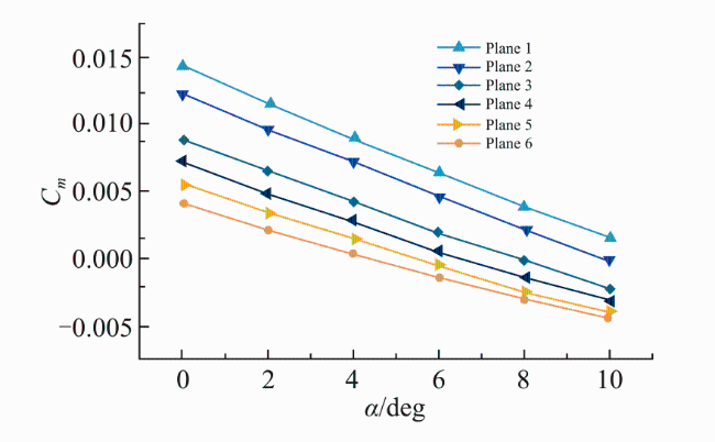
如图15所示,脊形上表面外形对俯仰力矩系数具有一定的影响。0°攻角时,Plane 1的俯仰力矩系数Cm=0.01429,Plane 6的俯仰力矩系数Cm=0.00406,其主要原因为不同的脊形外形导致上表面压力分布不一致。随着攻角增加,脊形上表面导致俯仰力矩系数的差异逐渐较小。同时可以观察到俯仰力矩系数随攻角基本成线性变化,并且 <0,这表明乘波体具有纵向静稳定性。
3 结论
本文提出了一种基于B样条曲线的脊形乘波体设计方法,通过CFD数值模拟,对比了不同脊形上表面乘波体在不同攻角下的气动性能,主要结论如下:
1)在脊形乘波体设计中,引入B样条曲线设计方法是对该类型设计方法的一种补充,提升了型线的设计自由度。通过给定一定数量的控制点,就能生成一条光滑的曲线,使生成设计型线具有直观性。同时改变控制点的位置,设计型线便能随之相应的进行变化,使设计型线的调整具有便捷性。
2)脊形上表面设计赋予了乘波体内部容积的提升,为有效载荷布置提供了更优的空间,但是同样导致气动特性在一定程度上的恶化,在工程设计中需要对容积与气动特性进行一定的取舍。
3)脊形上表面的外形对最大升阻比及其对应的攻角具有较大的影响:当脊形上表面由“凹”逐渐变“凸”,会导致最大升阻比减小且对应攻角增大。在工程设计中,需要根据实际需求,对外形进行选取,以平衡最大升阻比及其对应攻角的需求。