0 引言
1 数值模拟
1.1 数值模型与材料参数
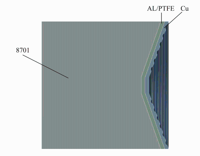
1.1.1 分析模型建立
1.1.2 材料参数确定
表1 无氧铜Johnson-Cook材料参数Table 1 Johnson-Cook material parameters of oxygen-free copper |
| ρ/(g·cm-3) | A1/GPa | B1/GPa | C0/(km·s-1) | C1 |
|---|---|---|---|---|
| 8.93 | 0.792 | 0.51 | 4.57 | 0.014 |
| m | μ | n | γ0 | |
| 1.0 | 1.3 | 0.26 | 1.67 |
表2 未反应活性材料参数Table 2 Parameters of unreacted active materials |
| G/GPa | A/MPa | B/MPa | n | c | m | Γ | C0/(m·s-1) |
|---|---|---|---|---|---|---|---|
| 0.666 | 8.044 | 250.6 | 1.8 | 0.4 | 1 | 0.9 | 1450 |
表3 反应的活性材料JWL参数Table 3 JWL parameters of the reacted active material |
| ρ/(g·cm-3) | D/(m·s-1) | A/MPa | B/MPa | R1 | R2 |
|---|---|---|---|---|---|
| 1.96 | 1390 | 4.9679 | -0.0361 | 7 | 0.6 |
表4 8701炸药JWL状态方程参数Table 4 Parameters of the JWL equation of state for 8701 explosive |
| ρ/(g·cm-3) | A/GPa | B/GPa | R1 |
|---|---|---|---|
| 1.78 | 581.4 | 6.8 | 3.94 |
| R2 | D | PCJ | V0 |
| 1 | 0.839 | 0.34 | 1.0 |
表5 混凝土材料参数Table 5 Parameters of concrete material |
| 剪切模量 /GPa | 单轴抗压 强度/MPa | 拉压强度比 | 剪压强 度比 | Lode角 相关系数 |
|---|---|---|---|---|
| 17.7 | 55 | 0.1 | 0.18 | 1.6 |
| 失效面 参数 | 失效面 指数 | 拉压子午比 | 压缩应变 率指数 | |
| 1.6 | 0.61 | 0.6805 | 0.028 |
1.2 结果与分析
1.2.1 刻槽宽度-深度影响毁伤区域与毁伤效果分析
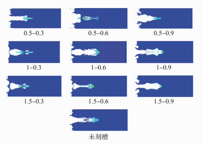
表6 各刻槽宽度-深度影响下混凝土侵彻深度的模拟结果Table 6 Simulated results of concrete penetration depth under the influence of various groove width-depth ratios |
| 刻槽结构参数 | 穿深/mm | |
|---|---|---|
| 刻槽深度0.3mm | 刻槽宽度0.5mm | 65.67 |
| 刻槽宽度1mm | 65.73 | |
| 刻槽宽度1.5mm | 63.51 | |
| 刻槽深度0.6mm | 刻槽宽度0.5mm | 67.11 |
| 刻槽宽度1mm | 70.26 | |
| 刻槽宽度1.5mm | 64.92 | |
| 刻槽深度0.9mm | 刻槽宽度0.5mm | 58.47 |
| 刻槽宽度1mm | 68.85 | |
| 刻槽宽度1.5mm | 64.33 | |
| 未刻槽 | 70.61 | |
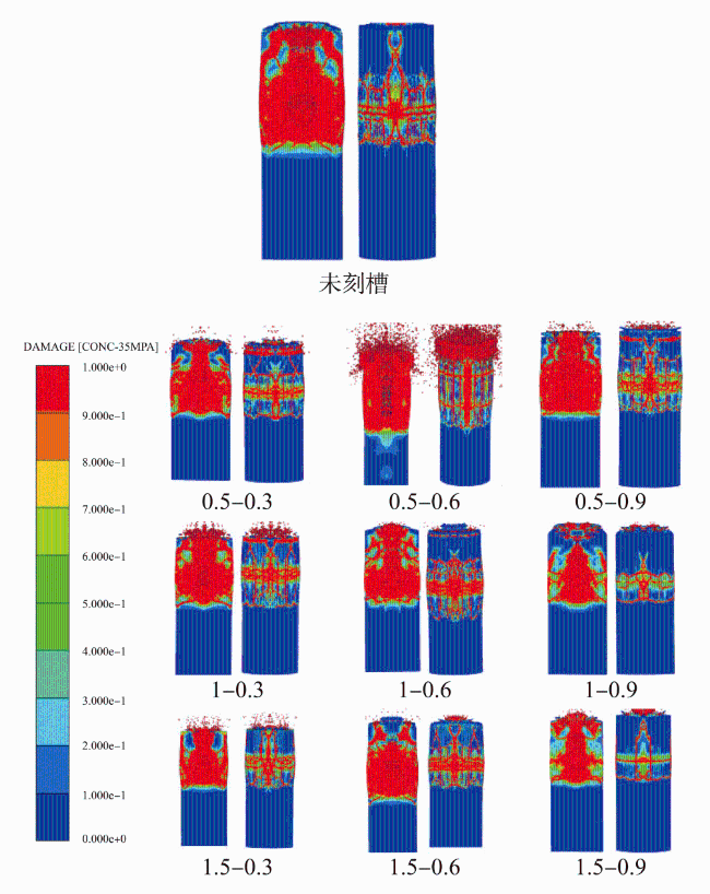
表7 各刻槽宽度-深度下释能后对混凝土最大毁伤深度的模拟结果Table 7 Simulated results of maximum damage depth of concrete after energy release under different groove width-depth conditions |
| 刻槽结构参数 | 穿深/mm | |
|---|---|---|
| 刻槽深度0.3mm | 刻槽宽度0.5mm | 68.6 |
| 刻槽宽度1 mm | 68.68 | |
| 刻槽宽度1.5mm | 68.18 | |
| 刻槽深度0.6mm | 刻槽宽度0.5mm | 75.21 |
| 刻槽宽度1mm | 78.94 | |
| 刻槽宽度1.5mm | 73.35 | |
| 刻槽深度0.9mm | 刻槽宽度0.5mm | 71.97 |
| 刻槽宽度1mm | 74.79 | |
| 刻槽宽度1.5mm | 70.33 | |
| 未刻槽 | 72.81 | |
1.2.2 刻槽间隔影响释能效果分析
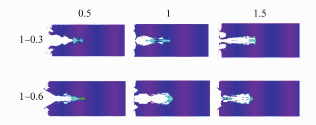
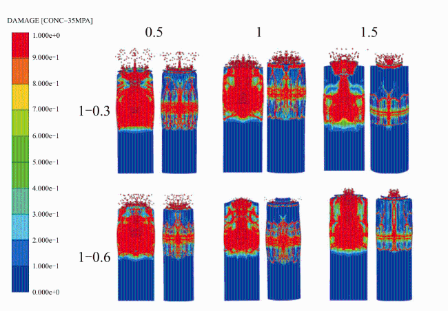
表8 刻槽间隔改变下混凝土最大毁伤深度的模拟结果Table 8 Simulaed results of maximum damage depth of concrete with varied groove spacings |
| — | 刻槽间隔 0.5mm | 刻槽间隔 1mm | 刻槽间隔 1.5mm |
|---|---|---|---|
| 刻槽深度0.3mm | 77.66 | 68.68 | 67.42 |
| 刻槽深度0.6mm | 75.98 | 78.94 | 73.52 |
1.2.3 刻槽份数影响射流释能情况分析
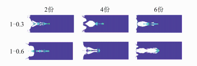
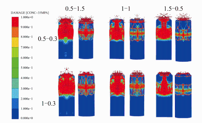
1.2.4 刻槽含能复合药型罩壁厚比影响释能效果分析
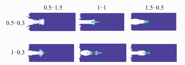
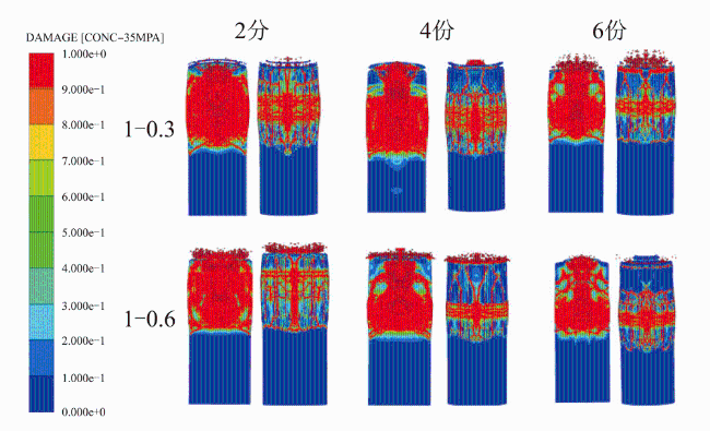
图12 刻槽后壁厚比变化对活性材料释能的影响Fig.12 The influence of the change in the wall-thickness ratio after grooving on the energy release of active material |
表9 刻槽后壁厚比改变时对混凝土最大毁伤深度的模拟结果Table 9 Simulated results of maximum damage depth of concrete with changed wall-thickness ratios after grooving |
| 刻槽结构参数 | 最大毁伤深度/mm | |
|---|---|---|
| 刻槽深度0.5mm | 壁厚比0.5-1.5 | 68.81 |
| 壁厚比1-1 | 68.6 | |
| 壁厚比1.5-0.5 | 69.1 | |
| 刻槽深度1mm | 壁厚比0.5-1.5 | 69.59 |
| 壁厚比1-1 | 68.68 | |
| 壁厚比1.5-0.5 | 69.91 | |
2 实验内容与现场布置
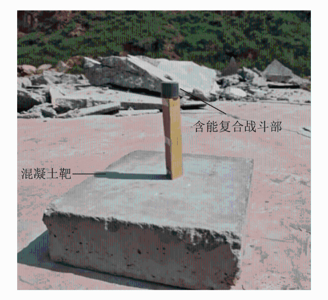
3 实验结果与分析
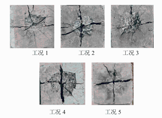
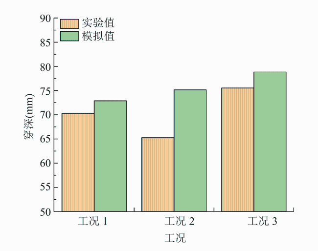
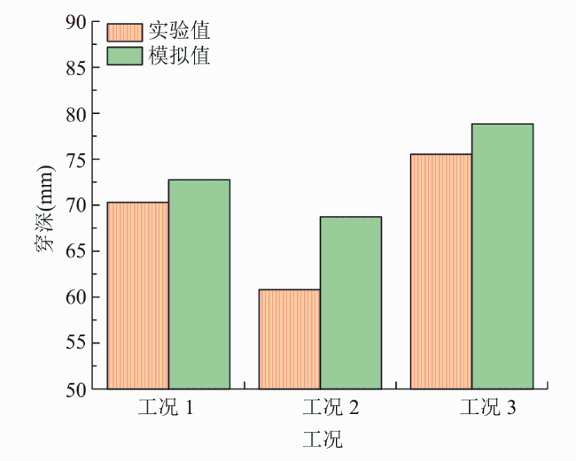
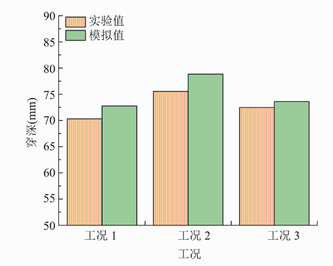
图14 各种刻槽影响下对混凝土的实验结果Fig.14 Experimental results of concrete under the influence of various groove parameters |
表10 各种刻槽影响下对混凝土的实验结果参数Table 10 Experimental parameters and results of concrete under the influence of various groove configurations |
| 工况 | 侵彻宽度/mm | 侵彻深度/mm |
|---|---|---|
| 1 | 124.47 | 70.32 |
| 2 | 152.83 | 65.38 |
| 3 | 137.25 | 75.63 |
| 4 | 172.38 | 60.72 |
| 5 | 141.92 | 72.45 |